Saturday, March 30, 2013

DAY 34 - Back to the dome.

As I wait for a few parts to arrive, I find that I have stalled a little in my progress.  It is not a matter of having "nothing" to do until these parts arrive, I just don't know what to do in the meantime.

So.... I played around with the "ights" a little on the front of the main body, trying to get the charge bay indicator lights working. On the CBI, there is a red, amber and green light that should show the status of the battery.  Currently, the only light that is lit is the red light, yet I have a full charge on the batteries.  I will troubleshoot that sometime in the future, as all I did today was scratch my head about it.

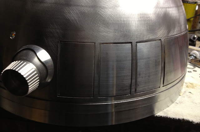
In the meantime, I got my dome bumps installed.  I had purchased a pair of resin bumps a while back, and the good lads at Astromech.net suggested 3/8" lag bolts.   This project took a whole 3 minutes to complete, and they look great.


I gutted the periscope housing of all of it's electronics and started working on a means of mounting the top plate.  After reviewing a number of reference photos, I noticed that the periscope I own did not have the surrounds for the side light ports.  

A couple of pipe nuts (and a whole lot of grinding) later, and I had a set of surrounds.  The photo below shows what I started with on top, and the finished product on the bottom.


Here the ports are mounted on the side windows.  This is probably something that would go totally unnoticed, but once I saw them in the screen caps, I could not live without them.  Eventually, these will be cleaned up a bit more and painted white.


Next up came the task of drilling out recesses for rare-earth magnets inside the top of the periscope housing.  The magnets are set in these holes with J B Weld, and they are not coming out any time soon.


Eventually, I will bond a thin metal strip to the aluminum pie panel that will hold the top on the housing.  Think something about the thickness of a razor blade.  In fact, a razor blade may be used in the final assembly.


After getting the servo code running last week, I decided to get to the task of mounting a couple of hinges on the dome doors.  This is the first time the inner and outer dome have been separated in a while, and they came apart without a hitch.

Captive studs were used to secure the hinges to the inner dome, then a false door / backing plate was attached to the hinge.


A view from the inside of the dome showing the hinges.  You gotta love the 4-40 gold blinged-out nuts on the inside.  I found these at a Menards in some state during a recent work trip.  I like the look a whole bunch, and will have to seek out another Menards to see what stock I can pillage at another store.  Again, nothing that 99% of the general public will ever see, much less care about, but it does look sharp.

I had picked up 4 of these hinges from an Astromech.net member, and I am currently waiting for a few more to arrive so I can mount up the rest of the dome panels.


Back to the outside of the dome and the backing plates.


A little strip of Scotch super-bond double sided tape.


There we are - dome doors, mounted and ready to go.   Eventually, the backing plates will most likely be mounted with VHB tape or silicone - something that can be removed if need be.  

The doors do swing open, but there is a little problem with the available clearance.  They don't exactly open as wide as I would like them to.... so back to the drawing board on this one - I have to think how repositioning the mounting points will effect the arc of the hinges (if at all).


There we have it, a relatively slow day - most of it spent on the grinder making the surrounds for the periscope.  I am too excited about a shipment that will arrive next week.  Stay tuned for the surprise !


Sunday, March 24, 2013

DAY 33 - A day of rest

Not much to report here, other than I am all junked up on the Arduino coding.  I had an idea that once I started into the coding of the boards, I would not come back for some time.  The dialog in my head went something like this:


Dr. Peter Venkman: Scotty has gone bye-bye, Egon... what've you got left?
Dr. Egon Spengler: Sorry, Venkman, I'm terrified beyond the capacity for rational thought.

There is something really satisfying about taking pre-written code meant to do one function, and re-purposing it for multiple items.  Obviously, it is very difficult to do a Google search for "R2D2 random Servo movement code" and expect to get anything in return.  So, we are left to our own devices in order to accomplish our goals.

I hooked up a SainSmart Sensor Shield V5 4 Arduino APC220 Bluetooth Analog Module Servo Motor in place of the protoyping breadboard with all of the wires.

Here is the link to the product.  Best 7 and a half bucks I have spent in a long time.

http://www.sainsmart.com/sainsmart-sensor-shield-v5-4-arduino-apc220-bluetooth-analog-module-servo-motor.html


This "Shield" plugs in right on top of the Ardunio board and has a number of pins pre-soldered for the servos assigned to the digital output pins on the Arduino board.  It also has a nice power connection to power the servos independently of the Arduino board.

A little video of a couple of Clone Troopers doing some basic maneuvers.


I did test the Periscope lighting from last week, and I am happy to say that it still works !  Thank goodness for small favors.

I promise to get back to building something proper next week...


Saturday, March 23, 2013

DAY 32 - No building, Mo Coding

I believe that talking about programming is about as exciting as talking about insurance premiums for most people, so I will keep this short and sweet.

I did not venture over to the workshop today, instead, spent some time coding on the Arduino board to control the servos.  I found some code to enable a pushbutton switch to start the servo sequence, along with some really cool code to move the servos.  The results are shown below.  I was playing around with all kinds of movement.  Lots of fun, but difficult to keep straight what servo number is doing what at any given moment.

Fortunately, I have a good ability to read code.  I can't necessarily WRITE code, but I can understand it when I look at it.  Then, all that is left is to hack it up and make it mine.  Most of the code examples on the interwebs show you how to move a single servo 90 or 180 degrees.  I expanded this code to include 4 servos and, well, the results are shown below.


Eventually, I will use an Arduino MEGA that allows me to control more servos (up to 48 I believe).  This will be used to control all of the servos in the dome that actuate the doors, pie panels and move the Holo-Projectors.

The code for the pushbutton activation will be replaced with a remote switch to start the servos a-popin'

Friday, March 22, 2013

DAY 31 - (Well technically "evening" 31) - Servo num-nuns

After continued failure with the Sparkfun breakout board that was to control multiple servos, I decided to go into effective troubleshooting mode.  When trying to identify a problem with anything electric, you start downstream and move upstream with all of the components.

I tested all of the pins on the Sparkfun board and could not find any problem, yet the board got hot when powered up and there was that pesky smoke rising from various pin clusters on the board.

No matter what I did, the board (and code) would not work.  I find this terribly odd, as when I first hooked it all up - it worked flawlessly.  2 minutes later - nothing, then smoke.... and more nothing.  At times the servos would twitch, and then the smoke would come, other times, no movement, no smoke.... You get the picture.  It was just a bad deal all around.  I have to believe that I somehow fried the Sparkfun board, yet I have no idea exactly how I accomplished that.

Admittedly, the Sparkfun breakout board was a little beyond my pay grade, so I decided to go back to the basics of programming via the Arduino sketches.

I found a sketch that was written to control a single servo, and modified it to control 3 servos.  Ultimately, the Arduino community seems to be full of this methodology.  Hence the term "Hacker" that is used lovingly to describe the process and those who partake in it.

Here is the lovely mess that I created to power the three servos.


The Arduino Board which runs the code to move the servos is connected (and powered) to my computer via the USB cable.

In the lower left, a AA battery pack to power the servos independently from the USB power feeding the Arduino board.  Depending on how many servos you are controlling, the lack of power from the USB can cause the Arduino to reset.  It is suggested to power servos independently from the Arduino board.

The solderless prototyping breadboard in the center is the device that feeds the power and signals from the Arduino to the individual servos.

Them things on the right are the Servos.....

Here is a little video of the setup in action :


Yah, I know.... relatively uneventful, but this code will be scaled  to move all of the servos in R2's dome and eventually control the opening and closing of the doors and pie panels on his head.  Right now the code is written to run when the unit is powered up.  I will have to find out how to make the code run on some kind of input from a remote source (either the RC controller or a wireless RF signal).

I am really pleased with my first attempt at coding the Arduino board, as I took some base code found on the interwebs, modified it, and made it my own.  Most important : it did what I wanted it to do.

For those of you that want to see it / use it - here is the code I used.  Please be gentle, as I had no idea what I was doing, so there are probably 1000 different ways of writing this code more efficiently.  For those who don't know the first thing about code (like e about 3 hours ago), there is some logic in the programming language explained with the comments preceded by the " // " below.


// Sweep
// by BARRAGAN <http://barraganstudio.com>  (Hacked to pieces by ScottyK)
// This example code is in the public domain.


#include <Servo.h>

Servo myservo;
Servo myservo2;
Servo myservo3;  // create servo object to control a servo
                            // a maximum of eight servo objects can be created

int pos = 0;    // variable to store the servo position

void setup()
{
  myservo.attach(9);  // attaches the servo on pin 9 to the servo object
  myservo2.attach(10);  // attaches the servo on pin 10 to the servo object
  myservo3.attach(8);  // attaches the servo on pin 8 to the servo object
}


void loop()
{
  for(pos = 0; pos < 180; pos += 1)  // goes from 0 degrees to 180 degrees
  {                                  // in steps of 1 degree
    myservo.write(pos);              // tell servo to go to position in variable 'pos'
    delay(3);                       // waits 3ms for the servo to reach the position
  }
  for(pos = 180; pos>=1; pos-=1)     // goes from 180 degrees to 0 degrees
  {                              
    myservo.write(pos);              // tell servo to go to position in variable 'pos'
    delay(3);                       // waits 3ms for the servo to reach the position
  }


    for(pos = 0; pos < 180; pos += 1)  // goes from 0 degrees to 180 degrees
  {                                  // in steps of 1 degree
    myservo2.write(pos);              // tell servo to go to position in variable 'pos'
    delay(3);                       // waits 3ms for the servo to reach the position
  }
  for(pos = 180; pos>=1; pos-=1)     // goes from 180 degrees to 0 degrees
  {                              
    myservo2.write(pos);              // tell servo to go to position in variable 'pos'
    delay(3);                       // waits 3ms for the servo to reach the position
  }
 
 
    for(pos = 0; pos < 180; pos += 1)  // goes from 0 degrees to 180 degrees
  {                                  // in steps of 1 degree
    myservo3.write(pos);              // tell servo to go to position in variable 'pos'
    delay(3);                       // waits 3ms for the servo to reach the position
  }
  for(pos = 180; pos>=1; pos-=1)     // goes from 180 degrees to 0 degrees
  {                              
    myservo3.write(pos);              // tell servo to go to position in variable 'pos'
    delay(3);                       // waits 3ms for the servo to reach the position
  }  
 
}


Sunday, March 17, 2013

DAY 30 - More "ights" and soldering success

The interesting thing about this build is that I hit many "peaks" throughout the process.  After working on a particular part for a good part of a day, it just does not excite me that much... ADD kid is back.

Over the course of the build, I have been upgrading and experimenting with different parts to see what warns / what I like.  For the most part, I believe I have all that I need to get this guy done, it is getting down to the task of actually doing the deed.

The main power scheme scared the doo-doo out of me at first.  After a series of successful implementations, delivering power to whatever R2 needs is no longer an issue.  Actually assembling some of the finer electronics... that is another story.  Or at least was, until today.

Here is the periscope with the switch installed.  The switch in the upper right corner of the photo allows me to change the lighting mode.  It is a cool feature of this board.  By selecting a position on the rotary switch, a signal is sent to the microprocessor to run a certain code and, in turn, change the lighting mode.  The suggested placement of the switch is somewhere inside the dome.  I don't see a great need to change the mode that often, so I devised a way to fit it in the periscope body.  If I feel like changing  the lights, I can pop the periscope up, take off the pie panel and turn the switch.

So here is the test - can all of these guts fit into the periscope head ????


Another angle of the electro-sinews.  Note - the lights on the back have not been permanently mounted, and they are protruding from the periscope.  That will be addressed later.


Here we go - believe it or not,  it all fits !    You can see some of the rubber housing material stuck on with J-B Weld that I hacked up to block off some of the light cracks to inhibit light from bleeding into the other sections.


.. And another video of the unit in action - including use of the selection switch.


Once the periscope failed to capture my fancy, I turned to soldering up one of my many additional breadboards that will be used to control various devices.

Below is a shot of my soldering station.  FLUX is a MUST (as is really thin solder).


Honestly, this board took me no more than 20 minutes to put together.  About a week ago, I had watched a tutorial on "Proper Soldering Techniques" on the YouTube.  This is where I learned about the proper solder diameter and the use of flux.  The gentleman presenting the video said "Once you learn how to do it properly, it is actually quite difficult to perform a 'bad' solder".  Initially I thought, "yeah right, I can show you otherwise...."

The truth is, like anything else, once you find out how to do it right, you DO find it difficult to do it wrong.  Here are the results.  This breakout board is used to hook up the servos that will control the animated doors and pie panels on R2's dome.


Here is a shot of the front of the board - looking good.


A little bit closer - still nice.  Apparently there are different lengths of pin headers.  I must have purchased the "extra-long" variety, as these all had to be cut down to accept the servo wire connectors. Not a huge issue - a pair of electronic side snips made short order of that task.


Extremely excited to see my new creation in action, I went home and hooked up the board to my computer via an Arduino controller / microprocessor.  I uploaded the "sketch" that controls the servo motors and before you know it, I had 5 servos rolling back and forth.

The code and idea comes from this link.  


Indeed I had success just like the video shows... then I got confident.  I went in to change the code to bump the cycle time down and increase the throw of the servos.  That is where things started going horribly wrong.  For whatever reason, the code and board performed without a hitch with the first power-up.  Then, magically, my computer realized that there was something drawing an unusual amount of power from the USB port.  After that, I barely got the servos to twitch.....  When an Arduino board has too much demand on the processor, it "saves" itself by resetting.  This causes the code to stop, and it makes an attempt to restart itself.

Well - I never got back to the point of getting it working again.  Between the Arduino resetting itself, and the USB port disconnecting itself - I was back where I started, with a pile of wires and breadboards.  (Well soldered breadboards if I may)  Ultimately, the servo control board will be powered with a source from the distribution board within R2.  Unfortunately, I do not have an independent 5-6 Volt 3-4 amp power source sitting around home to use while prototyping and tweaking the code.  I do, however have one on order, as it will be used for this and a few other electro-goodies.

Soooooo close to having a really good feeling about the coding and use of the Arduino.... alas, that is what they make other weekends for.


Saturday, March 16, 2013

DAY 29 - IGHTS !!!!!

The periscope lighting drama continued for a bit today.  Everything worked after a week off... miracle of miracles.  Apparently my soldering skills are not as bad as I thought.  In the meantime, I picked up some super thin solder and some flux.  Hey, what do you know - that makes a HUGE difference.

For the son of a man who dealt with flux all his career - unfortunately, not much rubbed off in this arena.  If you plan to do some soldering on the electronic parts,  flux and thin solder is essential.  Here endeth the lesson.

 I got the lights all fit in the periscope, and again, they continued to work !

Here are a couple of shots of the periscope with the omnipresent blue tape to hold on something that needs holding on.  Like other parts, this thing is a work of art.  It never ceases to amaze me - the many talents of members in this group are limitless.


A View from the front.  The Pie panel on top is all wonky-jabbered - something that will be fixed once it finds a permanent home inside the dome.


And.... here it is all lit up !  This thing is incredibly bright.  This photo is also shot before I did a bit of work isolating the center lights from the side and top lights.  The center lights are so bright, they completely wash out the top tracer lights. 


Here is a video of the light kit in action, cycling through it's various modes of operation.  The video on camera is completely blown out by the luminous goodies emitted from the periscope.


I wanted to mount three voltage meters on R2 somewhere.  One to measure total system voltage of 24 volts, and two others to monitor the 12 volt and 5 volt supplies.

LOTS of wiring involved for these lights.  All of the power leads have Anderson Powerpole quick disconnects in car I need to remove the front skin for maintenance.


Everything hooked up and ready to go !

Oddly, I watched a series of Mythbusters outtakes about an hour before hooking this all up, and Adam Savage was shown mucking up something electrical.  He said"....Ahhhhh, and I have produced the blue smoke !!!!!  The problem with the blue smoke is that after it happens, electronics stop working"

This has happened twice to me in the past two weeks..... Once while trying to hook up an ammeter. Who knew they went inline with the power lead, and not connected to positive and negative leads (as shown on the back of the meter with little pictures).  "The Blue Smoke" experience #1.  You have never seen an old fart like me move so fast to shut the power off.

"The Blue Smoke" experience #2 happened when I got the front skins all wired up.  The really nice thing about the Anderson Powerpole connectors is that they are color coded.  Color coded so you hook up green to green, orange to orange, etc, etc.... Sounds simple, right ?  When I powered the unit up to test the voltmeters, POOOOOOFFFFF !!!!!!  Fast action ensued to switch the main power off.  I figured I somehow fried one of the new the voltmeters.  Nope, I had the power to the PBI and Logic board switched !  D'OH.  Face meet palm.  There it was, I had connected the green powerpole to the yellow and vice versa.  Fortunately, the electronics still worked after I hooked the unit up in the proper manner.  Bullet dodged.  I immediately went and picked up one of Kaden's books to re-learn my colors.


Closeup of the volt meters.  I really wanted to have three colors, but they only made two colors in this particular unit.  Who knows, I may swap out the red meter for another blue someday.

Steady rocking, showing 5 volts, 12.6 volts and 24.6 volts.  Function factor = 0, cool factor = at least 87 or 88.


A little wider shot of the lights and such.


Here is a video of Kaden rocking a new skill.  When we first showed him the lights, he took 3 steps back and shook his head, saying, "No, No, NOOOO !"  I believe it scared him to the point of filling his Huggies.

Ten minutes later, with the camera on, he is proud to show off his new skilz !


And yes, Kaden calls him Too-Too.  Just when I get my parents to call him R2..... I fear he will forever be known as "Too-Too".  Who knows, maybe Disney will pick us up for a new series called "Dott and Too-Too".


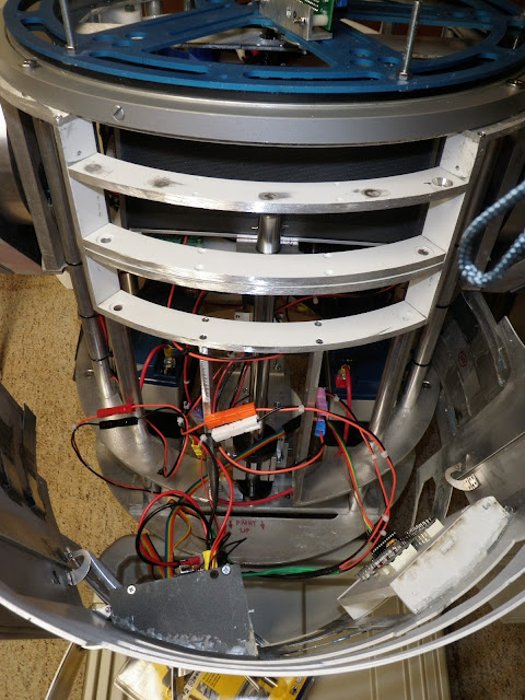
A view from the center vent to the internals.  Eventually, I plan to clean up the routing of the wires.  As of now, it is all about getting the things to work.  Pretty is not in the equation, that will come later.


A view from the top.  Believe it or not, I still have a very good idea about what each and every one of these wires feeds and serves.

R2 had a constant buzz coming from the speaker when he was not "talking".  After a little research on the Astromech boards, I installed a ground loop isolator on the audio output for the Bose speaker.  Works like a charm.  Think of the sound that may result from engine noise in some car stereos.   The speaker is absolutely silent until a signal is sent from the iPod via bluetooth. 


I have very exciting news about some parts I acquired this past week.  They will be featured in upcoming posts - stay tuned !!!!!


Sunday, March 10, 2013

DAY 27 & 28 - Can't say I didn't warn me....

It has come time in the build to work on more electronic goodies.

For the most part, the wiring of the motors and drivers has gone really well, and I am extremely pleased with the results.  I knew the day would come that I had to do some soldering on breadboards... and I was not looking forward to that day.

Over the past two weekends, I have been working on soldering and mounting the following:

     - Data Port Logics
     - Charge Bay Indicator
     - Periscope lighting kit

Wiring = easy, soldering = well, let's just say I need some practice.

Here are some photos to show you the good and bad of the past couple of build days.

Good : A nice power distribution board from Astromech.net member Dan S.   This board has a built in USB power port along with 3 ea. - 5 volt, 2 ea. - 9 volt and 3 ea. - 12 volt pass through terminals.  I swapped out the usb power source I was using for the Bluetooth extender, and I am now using power directly form this board.  I may hook up the USB power charger later, simply because it would be cool to charge an iWhatever off of this R2 unit.


Here is the power board mounted on the cross brace on it's own cutting board panel.


A top-down view of the Zagros robotics power distribution board (on the right), and the Club built board (on the left).  It is scary to think that I may actually use all of these outputs for the various lights and shiny-blinky-bling that I am adding to this increasingly complicated metal mound.


Last weekend, Dad jumped in and worked on a mount for the Bose speaker that will be R2's voice.  A simple aluminum bar was used and mounted with the screws that hold the now removed leather cover.  


Dad test fitting the speaker on the mount.


... and the results are perfect !


Here is a side view of the speaker mounted within the body.  I have a much better feeling with this mount as opposed to the velcro that was holding it in previously.


This little device and it's associated boards kicked my little behind for a while.  With all of the wires that  need to come off of the back of the light panel, it is difficult to find a place to mount the Arduino board that controls all of the random blinking of the lights.  This board sits on the inside of the outer skins, and needs to have clearance with all of the the other pieces parts that are already inside the frame.  It was mounted four times before it finally fit into the body.  (The photo you see below is either try 2 or 3.....)


That little Arduino board runs the code for the Data Port and Power Bay lights.  Completely useless in the scheme of things, but, when it is running, it looks great.  What made this difficult was getting all of the wiring quick connects from the skin mounted lights to the inner body.  If there is a need to service R2 in the field, and I need to pull the front skins off, I will need to disconnect all of the power easily.  The Anderson Powerpoles are great little connectors, and are used ad-nauseum on this assembly.

I also opted for a switch that would turn the front panels on and off.  This added some time to the project, but it looks cool, and I figure, unless he is standing still, there is no need for the lights to be running.  It will also be cool for people to flip the switch and see something happen.... (IF I let them get close enough)


My new obsession - heat-shrink wire thingies.  Yeah - they are really easy to use and look great to finish off connections.


Here is a shot of the Power Bay indicator.  The lights below the switch are to show the condition (charge) of the battery.  Currently, there is only one light lit... the red LED.  I believe I will need to tweak the code on the Arduino board to get the amber and green lights to work.


On the other side of the body is the Data Port.  Lots of random movement in these lights - really sweet, but again, nothing but bling.  They serve no purpose other than to be cool.


Somewhere in the past two weeks, I received a set of aluminum ankles.  These things are beautiful.  Now I can A: wait for a run of aluminum legs..... B: work a set of wooden legs into the aluminum ankles.  I know that if I take the time to mount the wooden legs, the aluminum legs will become available through the club, and I will once again be building for the experience.

Instead of waiting a couple of years to upgrade certain parts, I find myself upgrading as I build.  That is upgrading AFTER I have assembled something.  The dome is a prime example... fiberglass to Aluminum.  Patience would be a good practice, but I am learning all the time.


The ankle cylinders were mounted in about 5 minutes and look really good.


Good luck finding the required spacer and bolt at Home Depot or Lowes..... Luckily, an Ace Hardware opened up about 5 minutes from home, and they have EVERYTHING.  Ace has always been a throwback to old-school hardware stores.   They have ALL of my business from this point forward.  Home Depot and Lowes - you have my permission to close as many stores as you wish.


This is the bolt that will support R2 on his outer legs.  


A show of what will be, and what will was.......


I also installed a battery condition meter on the back board.  This meter shows the available charge left in the battery.  I am not exactly sure how accurate it is, as I recently charged the batteries, and it is on Full at the moment.


This little hunk of PCB was my nemesis this weekend.  As stated before, my soldering skills are lacking, and this did nothing but prove that fact.  You ask - how difficult is it to solder a dozen LEDs onto a breadboard.... I asked myself that - and I was WRONG.  It was a royal P.I.T.A.

As Mom and Dad headed out this afternoon, they asked what I was going to work on.  My response, "Swearing at a piece of plastic and wires".


After exhausting every expletive in my vernacular, I finally got this thing wired and working.

Then I shot a victory video !  Came home to find out that I did not shoot the video.... I blame a combination of frustration and elation on the fact that it actually worked for not noticing that the REC light was, in fact, not blinking.  I will get a video of this gem with next weeks update.


All of the wiring and PCB will fit inside the periscope housing below.... another task that I am not looking forward to.  The good thing is that once it is in place, it does not need to come out (unless my crappy soldering rears it's ugly head).


More of something next weekend.... I am at the point that I have a TON of stuff going on in this build.  The past two weekends were really thin on the victories, and long on the process.  Hopefully I will return to my old form in the upcoming weeks.