Friday, February 15, 2013

DAY 26 - A Friday night session

I plan for this post to be short on words, as it is late, and it is the end of a very long week.

I arrived at the workshop at around 8:00 and got right to installing a number of new electronic goodies in R2.  The first order was to get some of the wires from the electronics bay organized, as I was on a mission to add even more sinews to the tangled web of plastic shrouded copper spaghetti.

First, I needed to make some room inside the body for the electronic board "annex" that holds the power distribution board and the slip-ring distribution board.  I drilled mounting holes in the crossmember of the frame.


A little closer look at what I am babbling about.


These screws then run through the 24V to 12V converter box.


On top of the converter box, I mount the secondary electronics bay.


A little closer look.  I am happily surprised I found some bolts that were actually the exact size I needed.


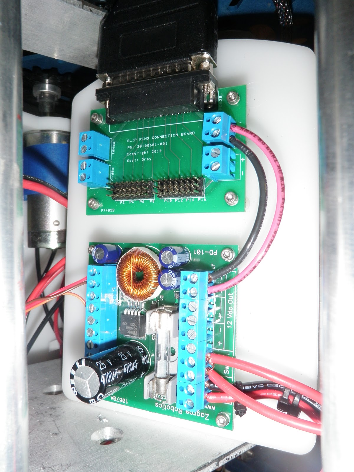
A view from a step back.  You can see the parallel port hookup that sends the power to the dome through the slip-ring.


Things are going extremely well at this point.  Then - I go to hook up the power lead that goes to the slip-ring, and ..... DARGH .... too short.

Not to worry, a quick 90 degree rotation of the slip-ring board, and the wire fits.


My sound setup.  I weighed a lot of options (meaning, I purchased a couple of things... and decided on the bluetooth sound setup).  I really fear the coding of the sound boards CFIII or other available sound boards, not to mention hooking up the controls to a 12 or 16 channel receiver.   I am very comfortable with the ReSounder IPod touch app that allows you to create unlimited custom soundboards.  These soundboards will hold all of R2's beeps and blurts and play through a Bose bluetooth speaker.

Concerned about the range of bluetooth, I found a bluetooth range extender.  This extender reportedly extends the range of a bluetooth signal from the default 10 meters to a whopping 100 meters.  So, I bypass the Bose bluetooth speaker, use the Miccus Range Extender as a receiver, and use the audio output to plug into the aux jack in the back of the bluetooth speaker (now simply a powered speaker with the bluetooth disabled).   I gotta say, this thing just works.  Upon testing, I had the speaker inside of R2, turned it up, went to the second floor of the house and heard him beeping away in the basement. So far, I am really impressed with the range of this device.

The unit is small, and can be used to transmit or receive a bluetooth signal.  I put the device in receive mode, literally in a second, it is hooked up with my iPod touch.  Most bluetooth devices take a while to sync up with your source,  I have to believe with the strength of the boosted signal, it locates the iPod and hooks up really quickly. 


Here is a shot of the back of the range extender with the various audio outputs and inputs.  Again, I am using the device in output mode (as a receiver) - and sending the signal to the Bose speaker through the Line Out / Rx Audio Out jacks.


Gotta have some power for the extender and the speaker.  I picked up a Motorcycle USB power supply that accepts input from 6-24 volts and outputs a 5 volt usb connection.
The Bose speaker did not have a power option via USB, so I picked up a car charger for the speaker, and hooked it up to a 12 Volt car power supply port.


Happy/dumb luck experience #422 : the bluetooth extended fits in the cutting board handle perfectly.  Like it was meant to be there all along.  The video below shows how this fits in the top of the electronics bay.


A shot from the front, showing the speaker mounted behind the utility arm bays.  I figure that the Large Data Port opening right below the dome will allow a good amount of sound to escape from the body once the skins are attached.  Oh yeah... the skins.  I have still not attached the skins to see if all this work actually FITS inside the little guy.  If it does not, I presume a Hiroshima-style F-Bomb will be heard far and wide.  Keep your ears peeled.


And as mentioned earlier, here is a video of all the powered up goodies working in unison.  I still have to adjust the new motor holders and casters, as they are not performing well now.


... and last but not least - a set of yummy aluminum spacers from Al Eisenmann from the Astromech boards.  Al and his family (and his R2) were honored with an appearance in an upcoming WIRED magazine article.  Kudos to Al and his family for this experience !


And a SWEET video featuring a number of my 501st brothers and sisters.


A little surprise with the set of spacers - R2-D2 Builders Club sticker !!!!  (It's all about the swag in case you did not hear).


Saturday, February 9, 2013

DAY 25 - R2 gets a couple of visitors !

Earlier this week, I got in touch with my cousin Darrell and asked him if he would like to see R2 in person.  After talking with him a little while, I found that he has been an avid reader of this blog.  He certainly knew his stuff !

Darrell works for a company that makes remote operated vehicles (think Big Geek and Little Geek from The Abyss).  I wanted to tap his knowledge about wiring and power distribution way back when I started this project.

Darrell and his wife, Heather, showed up with lunch !  I would like to extended an open invitation from this point forward - come and see the build process -  the only requirement is to feed the builder.  R2 gets his nourishment from OOOOOHs and AHHHHHs.

Here is Darrell working on the little guy.  He is probably the only person other than my Dad that I would even consider wielding a tool near R2.   Keep in mind, this guy makes bots the size of toasters that work in cooling lines for nuclear power plants.


I think I recall Darrell saying, "Can we build one, huh ?... huh? Can we ?!?!?!?"  ... and Heather responding with something along the lines of, "ahhhhhh...... Nooooooo."


As I told Darrell and Heather, at any given time, I have no idea what I am going to work on next.  As I was showing off some parts that were not installed, we came across the slip-ring that I bought a long time ago.  Darrell and Heather both talked about the tech behind the device and before you knew it, we were working out ways to get it installed.  

The data cable that carries the signal is too large to fit through the center hole in the dome plate and the frame.  Various ideas were bandied about as Darrell tested all of the pins on the socket with a multimeter.  Turns out every one of the pins except one was a live lead.  My assumption was that it probably had a couple of pins wired to carry power and ground.  I could not have been more wrong on this guess.

Below is the board that has an identical twin - one board sits inside the dome, and the other in R2's body.  The slip-ring allows power to be transferred through the cable while the dome spins without tangling the wires.  Darrell explained that the barrel of the slip-ring has connectors like teeth of a comb that allow contact within the rotating shaft.  The two top wire connectors are for straight power, the lower two connectors are to power the 16 individual servo power strips along the bottom.  All told, this makes for 24 very small wires housed in the Parallel connector.  Think old-school printer cable, and this is what the hookup is made from.

Currently (electro-jibberish-pun included at no charge) I only have the 12 volt power lead hooked up to power the Teeces lighting array in the dome.  More goodies will be hooked up as I get more skills with the Arduino controlled servo libraries.  I have to say that I am really happy about the servo power bay on this slip-ring.  When I bought it, I had no idea what all of these pins were for - lack of knowledge = happy outcome with this purchase.

Here is the slip-ring mounted on the dome plate.  The parallel port plug was popped open, and allowed me to slide the wires through the existing hole in the dome plate.  I had to drill out the hole in R2's body to allow the same process.  Of course, on the first try, I mounted it upside down, and it immediately tangled the wires.  Disassemble, rotate 180 degrees, reassemble and it works like a charm.


In the photo above, the pre-drilled holes in the dome-plate did not line up with the holes in the slip-ring flange.  I drilled a couple of holes in the dome plate, and fabricated a flange for the bottom of the ring.  This piece of aluminum is the remnant of cutting out the holes for the PSIs on the inner dome.  Lesson - never, ever throw anything out.  One mans scrap is another man's repurposed treasure.


A little work with some L shaped aluminum, and there it is mounted on the dome plate !  The twist in the cable is my fault.... If'n it weren't sloppy, it would not be made by me.


Below is the power bad annex.  The board on top is the inner body slip-ring panel, and the lower unit is a power distribution board from Zagros Robotics.  This power distribution board takes an input of 12 volts and steps it down to 5 ea. 5V outputs and 3 ea. 12 volt outputs.  The jumpers in the upper right are  taking the 12 volt signal form the power distribution board to the slip-ring board.

For those that are still awake - you might be asking ..... 12 Volt input ?  I thought this was running on 24 Volts.  Stay tuned to the bottom of the page for a video that will reveal a 24 Volt to 12 Volt regulator.  So - I go from 24 Volt Main power to 12 Volts for various electro-goodies and then have the option for 5 Volts as well.  As of now, the 5 Volt power output will power the RC receiver.

This reminds me of my first car, affectionately named "Schlomp 1".   "Schlompy" was a 77 Ford LTD that had an 8 track player (and more steel in a single door than most cars on the road today).  In college, I had a 8-track to cassette converter,  I used this with a Cassette to CD converter for a portable CD player.  I successfully spanned 25 years of audio technology in a single vehicle. Good times, good times indeed.


Back to the build.   The main power bay with an additional switch in the upper left hand corner.  The switch is for the Zagros Power Distribution board.  It HAS to be switched - something I found out after I hooked it up and no power was coming out.  Actually, the switch is optional, as I could have run a jumper between the switch inout, effectively making the board always "on".  I had a couple extra switches, so I threw one on the bay board and gave it some 24 Volt juice to power the LED light in the switch..... Ya' know, as I always say "It aint cool if your chrome don't shine, and it aint less cooler if your switch don't light"


Here is a shot of the slip-ring board installed in the dome.  I have been having a lot of fun with the nylon standoffs on these little boards.  (It does not take much for this one, no siree, never has....)


Not only did Darrel and Heather bring lunch - they brought a little gift for R2 - his very own handy-droid tool !  He approves.


... And as promised, a little video showing off the Electronics bay/board.  A virtual tour of where all the power goes.  This plan started in my head, and came to reality by buying a lot of parts, and throwing them all together.  I still have a MAJOR concern about the skins fitting on with all of the goodies installed.  It is not a huge issue, as I have room to reconfigure the items on the cutting board, but if I don't HAVE to move stuff around, that would be very nice.  Of course, I could have put the skins on to make sure all of this stuff was going to fit..... but then I would not have anything to complain about in future blogs.


And a last parting shot of the little guy


I imagine the next task will be addressing the new scooter motor holders in his feet.  The casters are getting caught up within the foot shells, and causing the scooter motors to labor until the "break free".  R2 does not run nearly as smoothly as he did.  In the end, I know the new motor mounts will be great, but as of now, they are a step backwards in my progress.  I had to tweak the Acrylic mounts before they were good to go, I just have not spent same time on these mounts.

Friday, February 8, 2013

DAY 24 - Happily Wired

So on this fine day, I decided to get to work on the wiring and electronics bay for my little Astromech buddy.  This will make showing his moves off a little more easy, as getting my ad-hoc wiring together in the past was quite a chore.

First off, I had to get the rear support bars in position so the threaded holes were facing front to back.  Who knew that the whole top plate would have to come off for this ?  When I first assembled the frame a couple of months ago, I knew what these threaded holes were for, but I did not think to line them up at the time.


I started with a good old fashioned cutting board.  (No, Mom, I did not use one of yours, I got this one at the Wal-Marts)  Drilled holes for the screws, and had to cut some slots to allow the center ring to fit in.


The first piece installed was the main power switch.  This thing is big, but I had ordered a good quality switch from Amazon that would handle 50 amps and 24Volts.  Apparently, these are used for automobiles, and they are quite robust.


Before we get to all the wiring, there are a couple of tools that I picked up, and bacon-saver is the flavor of these handy little numbers.

First up, a self-adjusting wire stripper.  This thing just plain works.  Put the wire in the jaws, set it to the right length that you wish to strip, pull - and there you go.  A really great tool that makes all of the wiring a simple chore.  I wanted to make the electronics bay as clean as possible, and no way would I have been so accurate and neat with the wire stripping with the traditional strippers.


Next up, a ratcheting wire-end crimping tool.  Again, this thing made short work of crimping the wire ends, and they all look identical.  


The last tool is the Anderson Power pole crimping tool.  I wish I could have used more of the power-pole connectors, but most of the wiring is... uh ...... hard-wired, so quick disconnects are not really required.


I picked up a 16 bay distribution and fuse box... OVERKILL is the name of this game.  I have no idea why I got this unit.  There was an 8 bay box available, but why not go with 16 ?   The truth is, this unit will handle the 24 volt power supply, and all I have running off the 24 volt supply is the leg motors and the dome motor.  I may pick up 2 of the 8 bay boxes and use one for 24 volt service and the other for the stepped-down 12 volt power, as I will have a number of items that need to be powered with 12 volts.

The two switches above the fuse box are for the power leads to the motors.  The motor controller has regenerative braking, which means the breaking of the wheels sends power back into the system.  (At least this is what I think I read...)  The bottom line is that if you have the droid powered up, and you push the little guy, the power from the wheels can feed back into the power matrix, and POOF, you can blow the motor controller.  The switches shut off the power between the motor controller and the actual drives.

You can see in the bench test that the switches are lit with green LEDs.  This little project kicked my hiney a bit.  I figured that the switches would illuminate when they were on... these switches have lights that are on ALL of the time.  It was pretty difficult finding a 30 amp switch that handled 24 volts AND had the added bling of lights.  Oh well - I am not sure when and why I will need to use these switches, but they look cool, and I learned a bit about wiring switches in the process.


Here is the motor controller mounted up.  The Leads that I am holding will serve the scooter motors with power.  I used the Anderson Power-Pole connectors on these, so I can disconnect the power and remove the legs easily.


A side view showing the nylon stand-offs that hold the motor controller off of the bay's board.


A little later, and the RC receiver and Dome motor controller are installed.  This power is being supplied by the 2 12 volt batteries.  WOOT !

I had to be very conscious of where the wires ran in the back of the board, because the board is VERy close to the rails that the center leg travels up and down on.  I HOPE HOPE HOPE that I did not mount anything that will interfere with the outer skins.  I threw caution to the wind on this one, using my keen eyesight and sense of distance to gauge where the electronics needed to fit in order to stay out of the way of the skins.  Only time will tell on this.... and if it is a fail, you may hear the expletives wherever you may roam.


The current state of the wiring inside the body.  A little ramshackle at the moment, as I need to find out exactly where the wires need to go so I can A: Easily remove the board for access to the inner-sanctum and B: allow for free travel of the center leg.  It is really amazing how quickly the space gets filled up inside this little guy.


Of course, I had to test out the power and new drive train(s).  Gotta say, that I am very happy with the results.  He moves, and nothing blew up, do I call that a victory.  The new scooter motor holders have a little issue.  I thing the caster on the legs may be a little high, as I found myself losing traction on the carpet.  This happened with the other holders, and was resolved with a little tweak to the angle of the center foot.

I got the aluminum bling mounted on the legs tonight as well.  Forgot my ankle cylinders.... I will get them on tomorrow.  Also sanded the horseshoes and they are dangerously close to paint - along with the rest of the leg pieces/parts.


Who knows what tomorrow will bring, I only have 2,017 more things to do.  Stay tuned, and see what I get into.


Saturday, February 2, 2013

DAY 23 - More Dome goodness.

As stated in my post yesterday, I was going to continue working on the dome today.

"No man born with a living soul  Can be working for the Clampdown"

         - The Clash, "Clampdown"

OK - so the clash has nothing to do with this build, but The Clash is one of my all time favs, and the dome got a clampdown last night.  This is the top inner dome bonded to the outer dome.

Only later did I realize that I should have waited, as I plan to mount servos to actuate the pie panels on top of the dome, and these could hove been mounted through the inner dome.... before it is bonded to the outer dome.

Oh well, research before you leap.  I was on such a roll Friday night, that I could not stop.  I figured it was a good opportunity to let the JB Weld set overnight so I could work with the dome in the morning. I am not that worried, as the JB weld is really something else.  It is a two part bonding agent will hold (according to the packaging) the very fabric of the universe together.  The only problem is that once mixed, it has the consistency of peanut butter - and it is rather difficult to spread.  So, lesson learned, read before you leap and many a show of tears you will keep.


I was on the fence about sanding the dome because of what a chore I have heard it can be.  The spin lines from the manufacture of the dome are quite prominent, and it is a choice of the individual builder to leave them, or opt for a shiny surface.  A few swipes of a sanding sponge later, I am one who will (eventually) have a shiny dome.  You can see a very distinct spin line cutting across the middle of the dome.  Hopefully, this process will not be as bad I have heard.... I will keep you posted.  

Ultimately, the result pays for itself.  Once complete, the shiny dome look is quite impressive.  Below is a photo of a dome that is a LOOOOOOOONG way from complete.


With the upper dome assembly pretty much complete, it was time to mount the inner dome to the lower flange.  The kit came complete with screws to mount the inner dome to the plastic ring, but they were torx drive (or star) screw heads.  Not only were they torx drive, they required the smallest bit known to man.  Dad and I have a good number of tools, including torx drive screwdrivers and bits.  These were micro sized, and I did not feel it was worth a try to the local hardware store to get a git for these screws.

I dove into my ever-growing box of screws, bolts, nuts and fasteners, and located a blister pack of 6-32 stainless steel screws.  What I actually bought these for, I haven't the slightest idea.  I am sure at some point in the future, I will need 12, and only have 6 because I used them on the dome.

Below is a photo of the inner dome mounted to the plastic ring and flange.  I had to take quite a bit of material off of the bottom of the inner dome in order to achieve the correct height.  I tried tin snips, the jig saw, a hack saw, the Dremel cutoff wheel....  Eventually, I ended up sanding the bottom edge down with my belt sander.  It took a while, and it rattled the dome to it's core.  Again, hindsight is 20/20 , and I tend to get a little myopic as I am working through this.  I left all of the hardware mounted as I was sanding - nuts came undone, captive studs flew across the room, and it even shot the Mini-Ardunio form the rear logic display under the workbench.  To save some sense of pride, I will call this a stress test, putting the dome through rigors that it would not see in 1,000 lifetimes.   

Once the screws were in place, I used a Dremel metal cutoff wheel to grind down the heads of the screws, as I don't see the need to remove this part anytime soon.


There is a strip in between the flange and outer dome.  This strip covers up the screws that mount the dome to the lazy susan.  Eventually this center strip gets a coat of blue paint.


Fortunately, I WAS thinking ahead before I mounted the dome to the flange.  The dome plate is designed to mount lifters for the various goodies that come out of R2's noggin.  These branches need to be centered on the openings of the pie panels.


A little off the top, please.  Sheesh - it may look like a disaster, but this is only the inner dome.  I honestly don't know how I did it, but the bolts that come up from the lazy susan bearing could have easily interfered with any number of things on the inside of the dome.  Two sets of logic displays, two PSI's, two holo-projectors - and I managed to MISS them all.  This was just dumb luck that it turned out this way, and if it weren't for dumb luck, I wouldn't have a brain at all.  (Or something like that)


Similar shot, different angle.


Happy as I was with my progress, one of the things that makes R2 recognizable is his Center "Radar Eye".  This is an interesting piece, as the inside of it follows the curve of the dome, so the mounting bolts are anything but straight.  I marked the holes for drilling and got to task.


... And you can see that I did not hit my mark as expected.  I had to do the same thing on the fiberglass dome, so I was neither surprised or worried about the ugliness of the holes.  They will be covered with the eye anyways.  Nobody will see the crappy drill and Dremel work.  Except for those who are still reading this post....


Ahhhh.. yes, I do believe that is about right.  Eventually, I want to pick one of these radar eyes up in aluminum, but they are extremely difficult to come by.


Next up the PSI spacers.  PSI = Processor Status Indicator for all you Nerds out there.  Actually, I had to look it up.  Not saying I am not a Nerd and all....  I just build R2 units while waiting for the Super Bowl to air.

In the lower left, all of the various pieces/parts are shown.  The pieces fit together like a fine lasagna, and on the right you see the complete unit.  All of these pieces are made from some form of silicone, nice and flexy.  The flange will mount the unit to the inner dome.   


"But you grow up and you calm down"... another Clash quote, from the same song as before no less  - sorry.  One assembled up and the other down.


Bonded to the dome with some JB Weld.  JB Weld Quick to be exact.  This stuff sets up in about 5 minutes, so no time for dawdling while working with this stuff.


The front PSI mounted in a similar fashion.  The flange needed to be cut down because this one is mounted lower on the dome, and the Holo-Projector is right next to it.


Amazingly, I did not need to use the wiring reference to get the Dome lighting kit hooked back up.  The length of the wires pretty much dictated which bundle goes where.  I am just happy tat I did not flit the wire harnesses from one board to another.  I could just imagine powering this up and... pffffft - POOF !  No more blinky, blinky for you, Mr. R2 guy. 


A little closer look at the wiring harnesses.  Eventually, I will run the wires along the inside of the dome, securing them with silicone.


So - what does it look like in action ??!??!?  In order to keep my blog followers happy, I offer another tasty video of my progress.

(And I just noticed that I have the PSI light on the wrong side.  The Blue/Red should be in front, and the Green/Yellow should be in back - this will be remedied next week.  Apologies for my Nerd-Fail.)


Oh yeah - I got a little paint on the little guy as well.  I could have spent the next 4 hours painting away, but I have to save some work for next weekend.

One of the paint methods is to use Mazda touch-up paint.  This particular color is from the RX8 - 2008 I believe, and it is a really nice match for R2's blue.  For a lark, I tried this on my power couplers.  This paint is extremely difficult to brush on.  Ultimately, If I am going to continue with this stuff, I will load up my airbrush and use this paint in it.  It was the end of the day, so I did not feel like breaking into all of that setup and cleanup.  The results, not horrible, but not anything to write home about.  I have a little clean-up to do, but these will certainly pass.


Leaving you with a shot of where he stands at this time.  Until next time - thank you for reading me up !