DAY 47 - Wrench slingin' and rearrangin'
Today was the day to address the back skin panel. The center leg cross brace and battery cage needed to be cut down so the rear octagon port would fit when the skin is mounted to the body.
Of course, I made this into a bigger task than it needed to be, but I finished off some parts that I was not completely satisfied with. To make a long story short, I removed everything from the inside from the inside bottom of the frame. As I was not pleased with his "stance" and the recurring problem of loss of traction on the drive wheels, I wanted to see if a little re-arranging would make a difference.
Here, the cross brace for the center foot gets a nice update. Both of the ends were angled off to allow the skins to fit. (Previously, I angled only the left hand side, but decided that I would keep things even and cut off the other side) I performed the same update on the rear cross brace.
Eventually, I will remove the markings on the frame... and eventually, I will clean up the wiring on the back of the electronics door. It works perfectly well - it just looks a mess.
As I stated earlier, R2 moved well, but there were often times that the drive wheel would slip, because his weight was not evenly distributed on all three legs. I had added a 1/2 aluminum plate to shim the center ankle up, and this improved matters, but the angle of the outer legs needed to be more upright than I liked in order for him to get around well.
For the fix, I went the other way with the center leg. Instead of extending it, I recessed the mounting plate into the body more. I also tested out the foot drives, mounting them with the drive wheel in front, rather than in the rear. Well - gotta tell you - I am not sure which one of those things did the trick, but R2 absolutely SMOKES right now. He is as fast and sure-footed as he has ever been. So much that I will have to dial back the radio control. At this stage, if he runs into anyone with 1/2 a head of steam, there will be a winner and a loser. (My money is on the 200 lb. metal dude).
Skirt removed and propped up on one of (too) many Lowes buckets for easy removal of the outer legs.
Didn't someone say something about "never being this naked again" ?????? Indeed, that was me, but you knew it wouldn't stick.
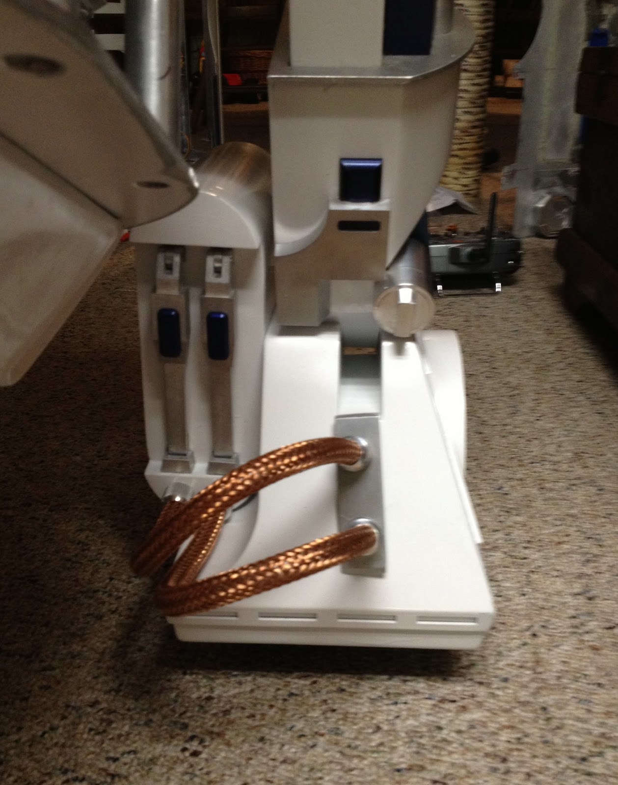
After the foot drives were reversed, and I got all of the wiring in place, I decided to tackle the battery box hoses. This was after I cut out a larger access port on the inside of the battery boxes. Since I reversed the drive wheel setup, I needed to adjust the opening in the inside of the battery box. Dremel cutoff wheel to the rescue. Ten minutes later, paint job intact, the battery boxes fit on the feet without a hitch.
Back to the hoses. The braided hoses are just that - braided hose, without anything inside. A small roll of 7/16" poly tubing to stiffen up the hose is in order. First I cut the host to length. I chose 14", knowing if it was too long, I could always trim back. Per spec, there should be 12" of hose visible from the tip of the knurled hose fittings.
Feeding the plastic hose into the copper braided hose was an adventure. Imagine a foot long Chinese finger trap. I had to inch the hose through by compressing a little bit at a time. It reminded me of a snake eating it's lunch. Once the internal support hose was ready, I taped off the ends to reduce unravelling.

\
To secure the hose inside the fitting, I notched out a piece of the inner plastic tubing to it would thread into the fitting easier. Once cut out, I taped the end again, and it slid right into place. It fits inside the fitting, just REALLY snug. I tried to pull the hose through without the notch, and the braided hose kept bunching up.
Once the hose was through, it would move with a little effort. To seal the deal, I used expanding screws. Some of the screws expanded really easily, others, I had to grip the plate with a set of pliers to keep them from twisting.
There you have it - the complete assembly. These things are not going anywhere anytime soon. I gave it my best "trying to break it, but not trying to break it" tug, and the hoses did not budge.
I threaded the knurled hose fitting back into the battery boxes, and filled the inside with two part epoxy. Here's hoping I will not have to remove these any time soon.
As another member pointed out in a comment in an earlier post, I had the "wrong" motor controller. The controller below is the Sabertooth 2 X 12. It is for medium duty bots with a suggested weight up to 150 lbs. Originally, I was just going to use this unit, but fear of frying the little board that controls the feet did not sit well with me.
This shot was also taken so I knew where the signal wires went when hooking up the new motor controller. (Including a Blue sharpie mark on one of the wires.)
This is the Sabertooth 2 X 25 - recommended for bots up to 300 lbs. It also gave me an opportunity to clean up the wiring into the unit - complete with spade terminals and heat shrink tubing.
Oddly - when I tested it out - the controls were completely reversed.... I did not thoroughly investigate the differences in the controllers, I only assumed that the hookup would be the same. A little tweaking of the Radio transmitter solved this problem.
The hoses are mounted into the battery boxes, but the foot plate is not permanently mounted as of yet. I had to cut down the inner thread of the hose fitting on the plate that attached to the feet, as the drive wheel is now in the front, and space is limited immediately inside the foot. Not a huge issue, but yet another thing that had to be modified due to my lack actually having a plan.
Left foot - looking shiny. You can see that the mounting plate is laying on the foot. This will eventually be locked down, most likely by finding really thin nuts that I can thread on the back of the fitting inside the foot..... without rubbing against the drive wheel.
When it comes time for final mounting, I will use my heat gun to soften up the inside hose a bit, and get it into a acceptable position. These things look really cool, and they are virtually crush-proof with the inner tubing.
Here is a shot of the three legs from the front. The left battery box needs to be tightened up a bit. You can also see the spacers that I put in the center foot mounting plate (the three bolts above the bottom tray). The battery boxes cages are re-installed, and heightened due to the center plate adjustment.
I also took time to swap out all of the bolts - using the correct size bolts, instead of using whatever I had available.
... just cause you know you wanted to see it again from 4 inches higher.....
Dome hinges are next. I am not really looking forward to this, as the four that I installed earlier worked, but did not open all that well. The hinges worked fine, but there is a great attention to detail on HOW and WHERE the hinges are mounted in order for the panels to open properly.
I will most likely remove the hinges that I have installed and re-work their location as I install the hinges on the top pie panels in the same expletive-laden session.